

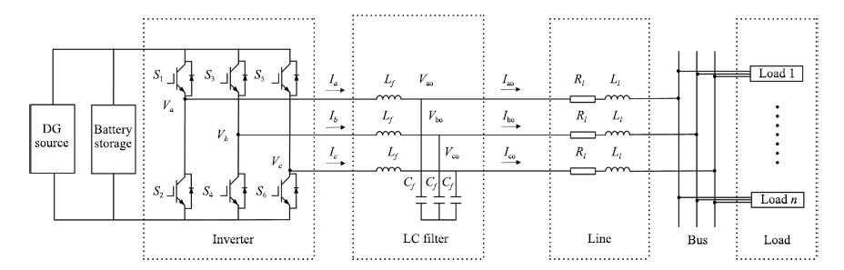
Figure
1.
Microgrid structure.
 Volume 4
Issue 2
Volume 4
Issue 2
IEEE/CAA Journal of Automatica Sinica
| Citation: | Zhanjun Huang, Zhanshan Wang and Huaguang Zhang, "Multilevel Feature Moving Average Ratio Method for Fault Diagnosis of the Microgrid Inverter Switch," IEEE/CAA J. Autom. Sinica, vol. 4, no. 2, pp. 177-185, Apr. 2017. doi: 10.1109/JAS.2017.7510496

|
IN response to societal requirements, microgrid system has received considerable attention [1], [2]. The reliability of the inverter is considered as an important factor to guarantee the high quality, continuousness, and safe operation of the microgrid. Serious impacts of inverter can be caused by an open-switch fault, and the secondary problems are also generated, which can cause other parts to break down. Hence, open-switch fault diagnosis for the inverter switch is very important for high quality power, safe and stable output of the microgrid system.
The diagnosis methods can be mainly classified into two categories: time-domain analysis method and frequency-domain analysis method. The frequency-domain analysis method is to adopt advanced signal processing technology to get the signal frequency changing law, which can reduce the false signal caused by the noise. In [3], the method is based on wavelet packet transform (WPT) to realize real-time diagnosis of three-phase inverter. Additionally, the time-domain analysis method is widely used in the signal processing of diagnosis for its fast detecting ability and simplicity. The time-domain analysis study of fault diagnosis methods of three-phase inverter switch is presented in [4]-[6]. The current or voltage signal is used as the research object to judge the fault. In [5], the method is based on the inherent feature of continuous voltage pulse-width modulation to realize fault detection. In [4], the radius of the current patterns is considered, and it is shown that it can not only detect the fault but also identify the location of the fault switch. The diagnosis method of [6] is based on the distortion of the input current and torque vibration in the system, in which both the inverter and rectifier switch fault are considered.
Although the inverter fault diagnosis methods are mainly presented in above two forms, the accuracy of the diagnosis method has not been an ideal result. For example, many methods, e.g., [4]-[10], are based on the distortion feature of the current signal or drive signal, which need to design an algorithm and the related threshold. When the number of switch is large or some interference signals appear, these methods are difficult to realize, which lead to inaccurate fault diagnosis of inverter. So, the switch faults are difficult to be accurately diagnosed.
Motivated by the above discussions, the purpose of this paper is to study fault diagnosis method for the microgrid inverter switch, which can realize an open-switch fault diagnosis. This method can improve the diagnosis accuracy, and is not influenced by threshold setting. The main contributions of this paper are summarized as follows:
1) Multilevel signal decomposition and reconstruction are investigated. The input signals are decomposed into the related coefficients of different frequency bands by the use of multi resolution analysis (MRA). Furthermore, the detailed signal information of the different frequency bands for three-phase current are obtained by the reconstruction of the related different level coefficients. It is conducive to express the detailed signal change law and improve the diagnosis accuracy.
2) The absolute average ratio process is investigated to extract the detailed signal change information. The signal decomposed in multilevel is processed by this method to achieve multilevel absolute moving average ratio of fault signal. Because the accurate signal variation laws are obtained, the signal feature of switch fault for any switch of inverter can be accurately distinguished. Additionally, it has the function of normalization and reduces the processes of design.
3) Artificial neural network (ANN) is used for the fault diagnosis of microgrid inverter to classify the signal feature. It is more convenient to be combined with above method and has the adaptive feature, which need not set related threshold of algorithm and has a high applicability.
4) In [6], [8], [11], [12], these methods need to set up the related threshold of algorithm for the three-phase current radius to diagnose the inverter switch fault. Compared with it, the proposed method in this paper has adaptive ability. The processes of detection and location are implemented at the same time. The design process is more simple and practical. Additionally, compared with [4]-[6], the proposed method is based on the multilevel decomposed signal feature extraction for absolute average ratio, which can obviously present the detailed signal change law and accurately distinguish the different switch status. Finally, compared with [13], [14], because of the absolute average ratio, the ANN design on the proposed method does not need the process of normalization, the outputs of ANN are more stable and accurate. The design is more convenient.
The remaining parts of the paper are arranged as follows: In Section Ⅱ, the circuit structure for microgrid is briefly described. In Section Ⅲ, the proposed fault diagnosis method is presented. In Section Ⅲ-A, multilevel signal decomposition and reconstruction are described. The decomposition and reconstruction effect is given. In Section Ⅲ-B, absolute average ratio process is presented. The effect of the extracted signal feature for part switch fault are given. In Section Ⅲ-C, the ANN classification method is introduced. The training and testing results are given. In Section Ⅳ, the overall effect of the proposed fault diagnosis method and the main feature data are given. Finally, the conclusion is provided in Section V.
The structure of the microgrid [15]-[18] is shown in Fig. 1, which includes DG sources, battery storages, DC/AC inverter, inductance capacitance (LC) filter, transmission line and many loads. In that, the DG sources and battery storages are applied to generate and balance the power. The LC filter is used to filter the output of the inverter. The DC/AC inverter is used to provide flexible operation and is connected to the grid. It consists of 6 insulated-gate bipolar transistor (IGBT) switches, and its driver uses pulse-width modulation (PWM) technique. The PWM is used to generate the switching pulses for the IGBT devices. It plays an important role in the minimization of harmonics and switching losses in the inverter, especially in three-phase applications [19].
In the system of microgrid, the transmission lines are equivalent to resistance ( Rl ) and inductance ( Ll ). The load sides are equivalent to impedance. Hence, the three state space equations of the microgrid system based on the Kirchhoff's law are obtained as follows:
|
[Lf000Lf000Lf][˙Ia˙Ib˙Ic]=[VaVbVc]−[VaoVboVco] |
(1) |
|
[Cf000Cf000Cf][˙Vao˙Vbo˙Vco]=[IaIbIc]−[IaoIboIco] |
(2) |
|
[VaoVboVco]=[Ll000Ll000Ll][˙Iao˙Ibo˙Ico]+[Rl000Rl000Rl][IaoIboIco]+[Zl000Zl000Zl][IaoIboIco] |
(3) |
where Ia , Ib , Ic represent the three-phase current output of inverter, Iao , Ibo , Ico are the current output of the LC filter. Lf and Cf represent the LC filter inductance and capacitance, Ll and Rl are the equivalence values of the transmission line, Zl represents the impedance of loads. The relationship between the three-phase current can be expressed as:
|
Ia=Imsin(wt)Ib=Imsin(wt−120∘)Ic=Imsin(wt+120∘). |
(4) |
From the microgrid structure (Fig. 1) and system feature (1)-(3), it can be seen that the microgrid outputs are affected by the inverter. There are important relations between the inverter and the output signal. It is an important guarantee for the high quality and safe operation for the microgrid system. The inverter faults usually cause many serious primary effects and some secondary problems. Hence, in this paper, the study of the fault diagnosis method for the microgrid inverter switch is important.
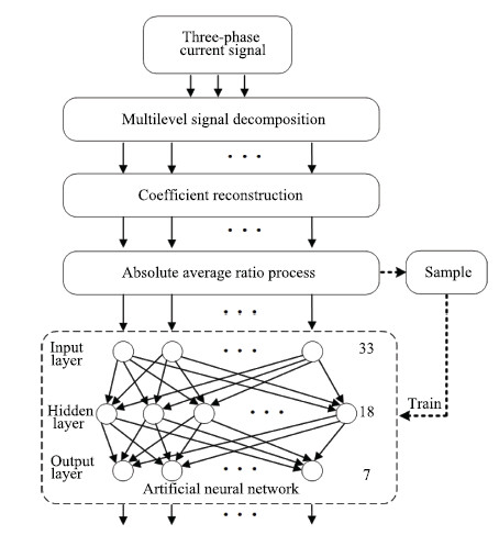
The multilevel feature moving average ratio method is shown in Fig. 2, which mainly includes multilevel signal decomposition, signals reconstruction in different frequency bands, absolute average ratio process, and artificial neural network (ANN) classification. The three-phase current signal obtained by sampling is used as the process signal. The input signals are decomposed into different frequency bands and the related coefficients are extracted by means of MRA. The detailed signals of different frequency bands are obtained by the reconstruction of the related coefficients. Furthermore, the detailed signals features of the different frequency bands are extracted by the absolute average ratio process. Finally, the ANN is used to identify the different switch status.
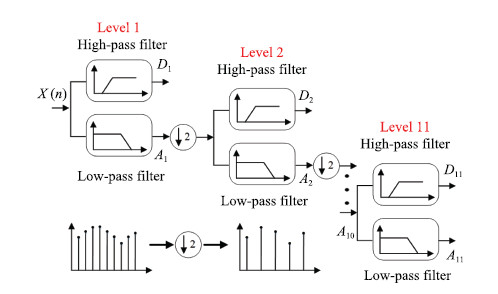
The multilevel signal decomposition and reconstruction are a process of the signal extraction at different levels. Multilevel signal decomposition is realized by the use of MRA to achieve different level decomposition coefficients.
Fig. 3 shows the decomposition principle of MRA. The MRA method has a good time-scale representation of a discrete signal at various levels of decomposition. It can decompose the discrete signal X(n) into approximate information and detailed information [20]-[22]. The scaling function ϕj,k(t) and the wavelet function ψj,k(t) are used for the signal decomposition. ϕj,k(t) relates to the approximate coefficients aj,k , and ψj,k(t) relates to the detailed coefficients dj,k at level j . The function ϕj,k(t) and ψj,k(t) are linked with low-pass filter coefficient h(n) and high-pass filter coefficient g(n) , respectively.
According to (5) and (6), the low-pass and high-pass filters based on the selected wavelet function ψj,k(t) and its corresponding scaling function ϕj,k(t) are constructed. It can be expressed in (9), the original signal X(n) can be newly defined as the j -level MRA representation.
|
ϕj,k(t)=2−j2ϕ(2−jt−k) |
(5) |
|
ψj,k(t)=2−j2ψ(2−jt−k) |
(6) |
|
aj,k=∑nh(n−2k)aj−1,n |
(7) |
|
dj,k= ∑ng(n−2k)aj−1,n |
(8) |
|
X(n)=2N−j−1∑k=0aj,k2−j2ϕ(2−jt−k)+J∑j=12N−j−1∑k=0dj,k2−j2ψ(2−jt−k) |
(9) |
where j and k are integers. J represents the level of decomposition. The approximate coefficients aj,k , detailed coefficients dj,k , the scaling function ϕj,k(t) and the wavelet function ψj,k(t) are related with the selected mother wavelet. The approximations and the details are the low-frequency and the high-frequency components of signal X(n) , respectively.
The limits for frequency bands are related with the level of signal and the sampling rate. The upper limit of detail D1 is half the sampling rate ( fs/2 ), and the lower limit is fs/4 . Therefore, the lower limit of its frequency band of the part Dn−1 of signal X(n) is the upper limit of the next detail Dn , and the bandwidth of the detail Dn is half of the detail Dn−1 . So, the detail Dn contains the high frequencies information [ 2−(n+1)fs , 2−nfs ], and the approximation An represents the low frequencies [0, 2−(n+1)fs ] [23], respectively.
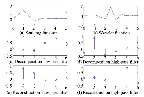
The ''db3'' of the Daubechies family has been used in a wide range of problems which contributes to the localization and classification disturbances [24]. Hence, in this paper, the ''db3'' wavelet is used to decompose the signal X(n) . The ''db3'' feature wavelets are shown in Fig. 4, which includes scaling function, wavelet function, high-pass filtering and low-pass filtering of decomposition, high-pass filtering and low-pass filtering of reconstitution.
The process of the signal reconstruction is opposite to the decomposition, and mainly realizes different level coefficient reconstruction to obtain different frequency bands signal. The coefficient adopts the cycle zero padding and is convoluted with the high-pass reconstitution filtering and the low-pass reconstitution filtering. The length of the different level signals and the original signal are the same.
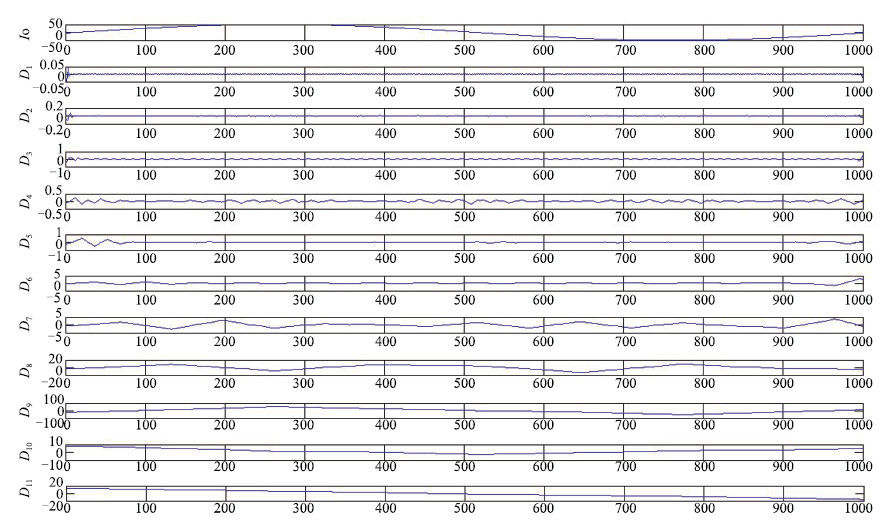
The reconstitution results of the different level signals for a periodic normal current signal are shown in Fig. 5. The result indicates that the original signal is decomposed into 11 different levels, and the detailed 11 level signals for three-phase current are reflected.
The detailed signals features for the different frequency bands are extracted by the absolute average ratio process, which can be expressed as:
|
μm,l(kτ)=1Nk∑j=k−N+1i∗m,l(jτ) |
(10) |
|
νm,l(kτ)=1Nk∑j=k−N+1|i∗m,l(jτ)| |
(11) |
|
ξm,l(kτ)=μm,l(kτ)νm,l(kτ) |
(12) |
where i∗m,l represents the obtained reconstitution signal of different level for three-current signal, m and l represent the phase ( a , b , c ) and different level, respectively. μm,l is the moving average value of phase current, νm,l is the absolute moving average of phase current, ξm,l is the absolute moving average ratio of signal.
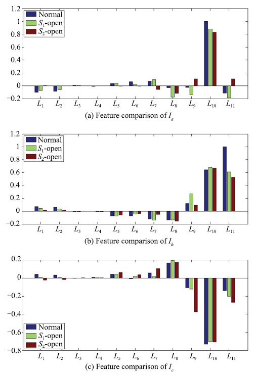
The results of absolute average ratio process of three-phases current signals at normal, S1 -open, S2 -open states are shown in Fig. 6. It is obvious that when the state changes, the proportion and size of the absolute moving average ratio of the 11 levels signal for three-phase current change. The change relation of them can be used to classify all the above states. Hence, because accurate signal variation laws can be obtained by this method, the signal feature of open-switch fault for any switch of inverter can be accurately distinguished. Additionally, using this feature processing method, only the calculation of the absolute value is required, which makes the method less computationally intensive and with smaller code size for fault diagnosis. Meanwhile, this method can simplify the processing steps. In general situation, the variable features of fault diagnosis often require normalization to realize the classification of fault. In this case, the absolute moving average ratio includes the normalization function, and the scope of the result is included in (1, -1).
To improve accuracy and realize the adaptive ability, the artificial neural network (ANN) is used to classify different inverter switch status. Nowadays, ANN is a powerful pattern recognition technique, and can realize many functions by training the laws, such as of pattern recognition or data classification, through a learning process [25], [26]. The structure of ANN is shown in Fig. 7, which has an input layer, a hidden layer and an output layer. The back propagation algorithm is used to minimize the sum of square error (SE) (14).

|
ek=Yk−Sk |
(13) |
|
SE=∑k(Yk−Sk)2 |
(14) |
where Yk and Sk represent the target value and the output value of neural network, respectively. Weight update function is
|
Wnew=Wold−η[∂SE∂Wold] |
(15) |
where η is the learning rate. In this paper, it is 0.1. The related weights are randomly initialized. The training precision is chosen as 0.01. According to the chain-backpropagation rules, the weights are tuned during the learning process. The forward paths of the ANN are provided as follows:
|
zj=NI∑i=1W(1)ijXj |
(16) |
|
yj=11+e−zj |
(17) |
|
lk=Nh∑j=1W(2)jkyj |
(18) |
|
Sk=11+e−lk |
(19) |
where Nh and NI are the number of hidden nodes and input nodes, respectively. The W(1) is the weights of the input to hidden layer. The W(2) is the weights of the hidden to output layer. The W(1)ij is a two-dimensional vector, which represents the weight between the i th node of input layer and the j th node of hidden layer. The W(2)jk is a two-dimensional vector, which represents the weight between the j th node of hidden layer and the k th node of output layer. lk is the input of the output layer. zj and yj are the input and the output of the j th hidden node, respectively. The weights from hidden to output layer are updated as
|
∂SE∂W(2)jk=∂SE∂Sk∂Sk∂lk∂lk∂W(2)jk. |
(20) |
The weights from input to hidden layer are then updated as
|
∂SE∂W(1)ij=∂SE∂Sk∂Sk∂lk∂lk∂yj∂yj∂zj∂zj∂W(1)ij. |
(21) |
The input of the ANN includes the 11 level absolute moving average ratio of three-phase current signal. Hence, 33 neurons are used as input for ANN.
The system is sampled with 50 kHz frequency, the 336 sets of data are randomly selected from 7 cases. The 231 sets of the 336 data sets are used for ANN training. The rest of the data is used to test the training effect.
For the structure of neural network, the input layer is the characteristic value of detection signal, and the detection signal is three-phase current. Every phase signal is decomposed into 11 levels. So, every phase signal has 11 characteristic values and the number all inputs to neural network is 33. The output layer represents the diagnosis results which has 7 kinds of results. Thus, the output neuron is 7. For the hidden neuron, firstly, the neuron numbers are obtained by the empirical formula Nh=√Ni×No ( Nh is the number of neurons of hidden layer, Ni is the neuron number of input layer, No is the number of neurons of output layer). Then, it is to do the cycle test within a certain range of 15 (Up and down the range of 10). According to the test accuracy of fault classification in Table Ⅰ, the hidden neuron corresponding to the highest accuracy is selected. When the hidden neuron is 18, the test accuracy of fault classification is 100% So, the final structure is 33-18-7.
| Inverter switch state | Target output value | ANN training quantity | Fault classification test quantity | Fault classification test accuracy (%) |
| No-fault | 1000000 | 33 | 15 | 100 |
| S1-open | 0100000 | 33 | 15 | 100 |
| S2-open | 0010000 | 33 | 15 | 100 |
| S3-open | 0001000 | 33 | 15 | 100 |
| S4-open | 0000100 | 33 | 15 | 100 |
| S5-open | 0000010 | 33 | 15 | 100 |
| S6-open | 0000001 | 33 | 15 | 100 |
 DownLoad:
CSV
DownLoad:
CSV
The model of microgrid system is set up by MATLAB/Simulink. The 6 kinds of inverter switch faults are diagnosed by the method mentioned in this paper. The open-switch fault is simulated by sending 0 driving pulse in the model. The main parameters are shown in Table Ⅱ.
| DC-link voltage | Inverter filter inductance | Inverter filter capacitance | Lines parameters | Power loads |
| 580 V | 1mH | 50 μF | 0.1 + j 0.11Ω | 20 kW |
DownLoad:
CSV
In this paper, the presented method belongs to the field of artificial intelligence [13], [14] that uses the characteristic value recognition for different switch status in inverter. Three-phase current signals are sampled in real time, the switch state of inverter is updated after every period T (0.02 s). When a fault appears, the state output is changed. In Fig. 8, the three-phase current signals and diagnosis result of the S1 open-switch fault are given, the Fig. 9 presents the current signals and diagnosis result of the S2 open-switch fault. The second illustrations of Figs. 8 and 9 are the corresponding switch status. In the output results, the highest output represents the corresponding switch state because the ANN training target is that the output 1 represents ''yes'' and the output 0 represents ''no''. The different colors represent various inverter states. The diagnosis time of S1 open-switch fault is 27.8 ms, and the diagnosis time of S2 open-switch fault is 28 ms. In the simulation results, the time of signal decomposition processing, characteristic value calculation and classification is about 40%T (8 ms), the diagnosis time is about 1.4T (28 ms). The main effectiveness of the presented method is to improve the fault diagnosis accuracy, stability and applicability for the multi-switch electronic devices.
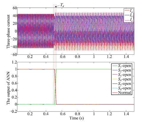
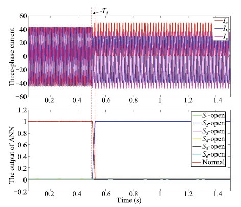
Table Ⅲ shows the output of neurons representing various switch states. The R1 - R7 represent the output of the diagnosis results. The highest value of neurons output is corresponding to the Table Ⅰ neuron target output, which represents the inverter switch status. It is obvious that the diagnosis results are the same as the target output. %There is a wide gap between the highest value of %neurons output and the rest.From Table Ⅲ, Figs. 8 and 9, it can be known that the output of highest values are higher than 0.99, the average values of the rest output are less than 0.001. That is to say, the output is relatively stable, there is a better diagnostic accuracy. Tables Ⅳ-Tables Ⅵ represent the feature component of 11 level signal for three-phase current. ξm,l is the absolute moving average ratio of signal. The data of 11 ξm,l is constituted of a set of component relations to represent the inverter switch state features. The scope of them is ( −1,1 ) and can be directly used in the input of the ANN.
| Inverter states | R1 | R2 | R3 | R4 | R5 | R6 | R7 |
| Normal | 0.9985 | -0.0005 | 0.0004 | -0.0011 | 0.0039 | -0.0011 | 0.0000 |
| S1-open | 0.0118 | 0.9958 | -0.0061 | -0.0002 | -0.0024 | -0.0048 | 0.0040 |
| S2-open | -0.0005 | -0.0018 | 0.9990 | -0.0026 | 0.0025 | -0.0031 | 0.0056 |
| S3-open | -0.0006 | 0.0002 | -0.0038 | 0.9943 | 0.0067 | -0.0024 | 0.0039 |
| S4-open | -0.0002 | -0.0005 | 0.0004 | -0.0003 | 0.9980 | 0.0002 | 0.0018 |
| S5-open | -0.0002 | -0.0001 | 0.0001 | -0.0005 | -0.0010 | 0.9999 | 0.0013 |
| S6-open | -0.0020 | 0.0004 | 0.0014 | -0.0009 | 0.0052 | -0.0008 | 0.9969 |
DownLoad:
CSV
| Inverter states | ξa, 1 | ξa, 2 | ξa, 3 | ξa, 4 | ξa, 5 | ξa, 6 | ξa, 7 | ξa, 8 | ξa, 9 | ξa, 10 | ξa, 11 |
| Normal | -0.1004 | -0.0841 | 0.0063 | 0.0086 | 0.0353 | 0.0631 | 0.0708 | -0.0280 | -0.0241 | -1.0000 | -0.1100 |
| S1-open | -0.0699 | -0.0580 | 0.0042 | 0.0001 | 0.0355 | 0.0242 | 0.0957 | -0.1755 | -0.1341 | 0.8777 | -0.1817 |
| S2-open | 0.0071 | 0.0031 | -0.0017 | 0.0008 | -0.0039 | -0.0063 | -0.0581 | -0.1202 | 0.1075 | 0.8278 | 0.1027 |
| S3-open | -0.1240 | -0.1041 | 0.0082 | 0.0125 | 0.0195 | 0.0573 | 0.0599 | -0.0640 | -0.0008 | 0.8927 | -0.0338 |
| S4-open | -0.0869 | -0.0715 | 0.0055 | -0.0084 | 0.0126 | 0.0368 | 0.0159 | -0.0459 | 0.0031 | 0.8742 | -0.0224 |
| S5-open | -0.0884 | -0.0717 | 0.0053 | 0.0049 | 0.0445 | 0.0552 | 0.0813 | 0.0232 | -0.0723 | -0.3997 | -0.2723 |
| S6-open | -0.1115 | -0.0912 | 0.0069 | 0.0106 | 0.0153 | 0.0570 | 0.0654 | 0.0283 | 0.0012 | -0.0382 | -0.1349 |
DownLoad:
CSV
| Inverter states | ξb, 1 | ξb, 2 | ξb, 3 | ξb, 4 | ξb, 5 | ξb, 6 | ξb, 7 | ξb, 8 | ξb, 9 | ξb, 10 | ξb, 11 |
| Normal | 0.0700 | 0.0578 | -0.0045 | 0.0016 | -0.0721 | -0.0696 | -0.1199 | -0.1346 | 0.1203 | 0.6446 | 1.0000 |
| S1-open | 0.0437 | 0.0352 | -0.0028 | 0.0028 | -0.0708 | -0.0444 | -0.1401 | -0.1363 | 0.2680 | 0.6769 | 0.6069 |
| S2-open | 0.0168 | 0.0139 | -0.0007 | 0.0028 | -0.0576 | -0.0345 | -0.0472 | -0.1533 | 0.0937 | 0.6658 | 0.5314 |
| S3-open | 0.1448 | 0.1229 | -0.0094 | 0.0107 | -0.0324 | -0.0549 | -0.0925 | -0.0495 | 0.0749 | 0.5229 | 0.3782 |
| S4-open | 0.0306 | 0.0246 | -0.0012 | 0.0012 | -0.0176 | -0.0129 | -0.0058 | -0.0515 | 0.0460 | 0.6040 | 0.8553 |
| S5-open | 0.0952 | 0.0796 | -0.0060 | 0.0061 | -0.0479 | -0.0522 | -0.0741 | -0.1015 | 0.0479 | 0.5883 | 0.6546 |
| S6-open | 0.0696 | 0.0568 | -0.0043 | 0.0004 | -0.0894 | -0.0621 | -0.1292 | -0.0902 | 0.1197 | 0.6278 | 1.0000 |
DownLoad:
CSV
| Inverter states | ξc, 1 | ξc, 2 | ξc, 3 | ξc, 4 | ξc, 5 | ξc, 6 | ξc, 7 | ξc, 8 | ξc, 9 | ξc, 10 | ξc, 11 |
| Normal | 0.0430 | 0.0350 | -0.0024 | 0.0074 | 0.0410 | -0.0098 | 0.0570 | 0.1671 | -0.1087 | -0.7313 | -0.1394 |
| S1-open | 0.0092 | 0.0079 | -0.0005 | 0.0032 | 0.0411 | 0.0200 | 0.0163 | 0.1922 | -0.1215 | -0.7012 | -0.2036 |
| S2-open | -0.0216 | -0.0158 | 0.0018 | 0.0035 | 0.0620 | 0.0361 | 0.1064 | 0.1739 | -0.3728 | -0.7077 | -0.2663 |
| S3-open | 0.0186 | 0.0144 | -0.0007 | 0.0041 | 0.0235 | 0.0098 | 0.0294 | 0.1215 | -0.0451 | -0.7470 | -0.0966 |
| S4-open | 0.0719 | 0.0577 | -0.0043 | 0.0083 | 0.0038 | -0.0324 | -0.0094 | 0.2057 | -0.0408 | -0.7614 | -0.0688 |
| S5-open | -0.0153 | -0.0105 | 0.0010 | -0.0010 | 0.0066 | 0.0032 | -0.0023 | 0.0558 | 0.1038 | -0.6744 | -0.1831 |
| S6-open | 0.0804 | 0.0672 | -0.0050 | 0.0163 | 0.0691 | -0.0148 | 0.1021 | 0.0789 | -0.3959 | -0.7401 | -0.2508 |
DownLoad:
CSV
In [6], [8], [11], [12], the methods need to set up the related threshold of algorithm for the three-phase current radius to diagnose the inverter switch fault. Whereas, from the process of the method design in Fig. 2 and the related fault diagnosis result, it is obvious that the proposed method has adaptive ability which needs not set up the related thresholds. The processes of detection and location are implemented at the same time. The design process is more simple and practical. Additionally, compared with [4]-[6], the proposed method is based on the multilevel decomposition signal feature extraction for absolute average ratio, which can obviously present the detailed signal change law and accurately distinguish the different switch status. Finally, compared with [13], [14], the ANN design of the proposed method does not need process of normalization, and the outputs of ANN are more stable and accurate.
In this paper, the multilevel feature moving average ratio method for fault diagnosis of microgrid inverter switch has been proposed. The proposed method has accurately detected and located the open-switch fault for any inverter switch in the microgrid. Meanwhile, it has the adaptive features, which does not need to set up the related thresholds of algorithm, and it has a high applicability. Particularly, multilevel signal decomposition and reconstruction has been investigated to obtain the detailed signals information of the different frequency bands for three-phase current. Additionally, the absolute average ratio process has been investigated to achieve multilevel absolute moving average ratio of fault signal. It also has the function of normalization and reduces the process of design.
Although the proposed method can be realized by simulation, it is difficult for the short-switch fault diagnosis in real experiments because the time between the fault initiation and failure is very small. However, if the ANN classification method is written into the hardware and the high-performance IGBT is developed, which has high current ratings and ability to handle short-circuit currents for longer time, then the short-switch fault diagnosis is possible to be realized by the proposed method.
| [1] |
R. Lasseter and J. Eto, "Value and technology assessment to enhance the business case for the CERTS microgrid, " University of Wisconsin, Madison Wisconsin, United States, Tech. Rep. FC02-06CH11350, May2010.
|
| [2] |
F. A. Mohamed and H. N. Koivo, "Online management genetic algorithms of microgrid for residential application, " Energy Convers. Manag. , vol. 64, pp. 562-568, Dec. 2012.
|
| [3] |
S. A. Saleh, T. S. Radwan, and M. A. Rahman, "Real-time testing of WPT-based protection of three-phase VS PWM inverter-fed motors, " IEEE Trans. Power Deliv. , vol. 22, no. 4, pp. 2108-2115, Oct. 2007.
|
| [4] |
U. M. Choi, H. G. Jeong, K. B. Lee, and F. Blaabjerg, "Method for detecting an open-switch fault in a grid-connected NPC inverter system, " IEEE Trans. Power Electron. , vol. 27, no. 6, pp. 2726-2739, Jun. 2012.
|
| [5] |
T. J. Kim, W. C. Lee, and D. S. Hyun, "Detection method for open-circuit fault in neutral-point-clamped inverter systems, " IEEE Trans. Ind. Electron. , vol. 56, no. 7, pp. 2754-2763, Jul. 2009.
|
| [6] |
J. S. Lee, K. B. Lee, and F. Blaabjerg, "Open-switch fault detection method of a back-to-back converter using NPC topology for wind turbine systems, " IEEE Trans. Ind. Appl. , vol. 51, no. 1, pp. 325-335, Jan. 2015.
|
| [7] |
U. M. Choi and K. B. Lee, "Detection method of an open-switch fault and fault-tolerant strategy for a grid-connected T-type three-level inverter system, " in IEEE Energy Conversion Congress and Exposition (ECCE), Raleigh, NC, USA, 2012, pp. 4188-4195.
|
| [8] |
Q. T. An, L. Sun, and L. Z. Sun, "Current residual vector-based open-switch fault diagnosis of inverters in PMSM drive systems, " IEEE Trans. Power Electron., vol.30, no.5, pp.2814-2827, May2015. doi: 10.1109/TPEL.2014.2360834
|
| [9] |
S. M. Jung, J. S. Park, H. W. Kim, K. Y. Cho, and M. J. Youn, "An MRAS-based diagnosis of open-circuit fault in PWM voltage-source inverters for PM synchronous motor drive systems, " IEEE Trans. Power Electron., vol.28, no.5, pp.2514-2526, May2013. doi: 10.1109/TPEL.2012.2212916
|
| [10] |
U. M. Choi, K. B. Lee, and F. Blaabjerg, "Diagnosis method of an open-switch fault for a grid-connected T-type three-level inverter system, " in Proc. 3rd IEEE Int. Symp. Power Electronics for Distributed Generation Systems (PEDG), Aalborg, Denmark, 2012, pp. 470-475.
|
| [11] |
P. Duan, K. G. Xie, L. Zhang, and X. L. Rong, "Open-switch fault diagnosis and system reconfiguration of doubly fed wind power converter used in a microgrid, " IEEE Trans. Power Electron. , vol. 26, no. 3, pp. 816-821, Mar. 2011.
|
| [12] |
I. Jlassi, J. O. Estima, S. K. El Khil, N. M. Bellaaj, and A. J. M. Cardoso, "Multiple open-circuit faults diagnosis in Back-to-Back converters of PMSG drives for wind turbine systems, " IEEE Trans. Power Electron., vol.30, no.5, pp.2689-2702, May2015. doi: 10.1109/TPEL.2014.2342506
|
| [13] |
M. A. Masrur, Z. Chen, and Y. Murphey, "Intelligent diagnosis of open and short circuit faults in electric drive inverters for real-time applications, " IET Power Electron. , vol. 3, no. 2, pp. 279-291, Mar. 2010.
|
| [14] |
S. Khomfoi and L. M. Tolbert, "Fault diagnosis system for a multilevel inverter using a neural network, " in Proc. 31st Annu. Conf. IEEE Industrial Electronics Society (IECON), Raleigh, NC, USA, 2005, pp. 1062-1069.
|
| [15] |
Y. Li and Y. W. Li, "Power management of inverter interfaced autonomous microgrid based on virtual frequency-voltage frame, " IEEE Trans. Smart Grid, vol. 2, no. 1, pp. 30-40, Mar. 2011.
|
| [16] |
Z. Y. Chen, A. Luo, H. J. Wang, Y. D. Chen, M. S. Li, and Y. Huang, "Adaptive sliding-mode voltage control for inverter operating in islanded mode in microgrid, " Int. J. Electr. Power Energy Syst. , vol. 66, pp. 133-143, Mar. 2015.
|
| [17] |
G. Diaz, C. Gonzalez-Moran, J. Gomez-Aleixandre, and A. Diez, "Complex-valued state matrices for simple representation of large autonomous microgrids supplied by PQ and Vf generation, " IEEE Trans. Power Syst. , vol. 24, no. 4, pp. 1720-1730, Nov. 2009.
|
| [18] |
F. Razavi, R. Torani, I. Askarian, A. Asgharizadeh, and N. Masoomi, "Optimal design of islanded microgrid using genetic algorithm, " in International Conference on Genetic and Evolutionary Methods (GEM'12), Las Vegas, Nevada, USA, 2012.
|
| [19] |
D. G. Holmes and B. P. McGrath, "Opportunities for harmonic cancellation with carrier-based PWM for a two-level and multilevel cascaded inverters, " IEEE Trans. Ind. Appl. , vol. 37, no. 2, pp. 574-582. Feb. 2001.
|
| [20] |
J. Kim, "Cell seletion through two-level basis pattern recognition with low/high frequency components decomposed by DWT-based MRA, " in IEEE Energy Conversion Congress and Exposition (ECCE), Pittsburgh, PA, USA, 2014, pp. 906-911.
|
| [21] |
V. R. Satpute, C. Naveen, K. D. Kulat, and A. G. Keskar, "Fast and memory efficient 3d-dwt based video encoding techniques with EZW based video compression mechanism, " in Transactions on Engineering Technologies, G. C. Yang, S. L. Ao, X. Huang, and O. Castillo, Eds. Netherlands: Springer, 2015, pp. 397-412.
|
| [22] |
G. F. Ju and A. Luo, "DWT application to real-time compression of power quality disturbance data, " Automat. Electric Power Syst. , vol. 26, no. 19, pp. 61-63, Oct. 2002.
|
| [23] |
J. Kim, G. S. Seo, B. Cho, W. Kim, J. Park, and T. Ishikawa, "Discrete wavelet transform-based characteristic analysis and SOH diagnosis for A Li-Ion cell, " in Proc. 7th Int. Power Electronics and Motion Control Conf. (IPEMC), Harbin, China, 2012, pp. 2218-2223.
|
| [24] |
K. Maleknejad, M. Yousefi, and K. Nouri, "Computational methods for integrals involving functions and daubechies wavelets, " Appl. Math. Comp. , vol. 189, no. 2, pp. 1828-1840, Jun. 2007.
|
| [25] |
R. Aggarwal and Y. H. Song, "Artificial neural networks in power systems. Ⅱ. types of artificial neural networks, " Power Eng. J. , vol. 12, no. 1, pp. 41-47, Jan. 1998.
|
| [26] |
R. Aggarwal and Y. Song, "Artificial neural networks in power systems. Ⅰ. general introduction to neural computing, " Power Eng. J. , vol. 11, no. 3, pp. 129-134, Mar. 1997.
|
| [1] | Zhongxin Liu, Yanmeng Zhang, Yalin Zhang, Fuyong Wang. Distributed Economic Dispatch Algorithms of Microgrids Integrating Grid-Connected and Isolated Modes[J]. IEEE/CAA Journal of Automatica Sinica, 2025, 12(1): 86-98. doi: 10.1109/JAS.2024.124695 |
| [2] | Yongyi Chen, Dan Zhang, Ruqiang Yan, Min Xie. Applications of Domain Generalization to Machine Fault Diagnosis: A Survey[J]. IEEE/CAA Journal of Automatica Sinica. doi: 10.1109/JAS.2025.125120 |
| [3] | Ke Chen, Wenjie Wang, Fangfang Zhang, Jing Liang, Kunjie Yu. Correlation-Guided Particle Swarm Optimization Approach for Feature Selection in Fault Diagnosis[J]. IEEE/CAA Journal of Automatica Sinica. doi: 10.1109/JAS.2025.125306 |
| [4] | Kailong Liu, Qiao Peng, Yuhang Liu, Naxin Cui, Chenghui Zhang. Explainable Neural Network for Sensitivity Analysis of Lithium-ion Battery Smart Production[J]. IEEE/CAA Journal of Automatica Sinica, 2024, 11(9): 1944-1953. doi: 10.1109/JAS.2024.124539 |
| [5] | Jiaxin Ren, Jingcheng Wen, Zhibin Zhao, Ruqiang Yan, Xuefeng Chen, Asoke K. Nandi. Uncertainty-Aware Deep Learning: A Promising Tool for Trustworthy Fault Diagnosis[J]. IEEE/CAA Journal of Automatica Sinica, 2024, 11(6): 1317-1330. doi: 10.1109/JAS.2024.124290 |
| [6] | Chi Ma, Dianbiao Dong. Finite-time Prescribed Performance Time-Varying Formation Control for Second-Order Multi-Agent Systems With Non-Strict Feedback Based on a Neural Network Observer[J]. IEEE/CAA Journal of Automatica Sinica, 2024, 11(4): 1039-1050. doi: 10.1109/JAS.2023.123615 |
| [7] | Dingxin He, HaoPing Wang, Yang Tian, Yida Guo. A Fractional-Order Ultra-Local Model-Based Adaptive Neural Network Sliding Mode Control of n-DOF Upper-Limb Exoskeleton With Input Deadzone[J]. IEEE/CAA Journal of Automatica Sinica, 2024, 11(3): 760-781. doi: 10.1109/JAS.2023.123882 |
| [8] | Bin Yang, Yaguo Lei, Xiang Li, Naipeng Li, Asoke K. Nandi. Label Recovery and Trajectory Designable Network for Transfer Fault Diagnosis of Machines With Incorrect Annotation[J]. IEEE/CAA Journal of Automatica Sinica, 2024, 11(4): 932-945. doi: 10.1109/JAS.2023.124083 |
| [9] | Xiang Li, Shupeng Yu, Yaguo Lei, Naipeng Li, Bin Yang. Dynamic Vision-Based Machinery Fault Diagnosis With Cross-Modality Feature Alignment[J]. IEEE/CAA Journal of Automatica Sinica, 2024, 11(10): 2068-2081. doi: 10.1109/JAS.2024.124470 |
| [10] | Yu Cao, Jian Huang. Neural-Network-Based Nonlinear Model Predictive Tracking Control of a Pneumatic Muscle Actuator-Driven Exoskeleton[J]. IEEE/CAA Journal of Automatica Sinica, 2020, 7(6): 1478-1488. doi: 10.1109/JAS.2020.1003351 |
| [11] | Hamed Kazemi, Alireza Yazdizadeh. Optimal State Estimation and Fault Diagnosis for a Class of Nonlinear Systems[J]. IEEE/CAA Journal of Automatica Sinica, 2020, 7(2): 517-526. doi: 10.1109/JAS.2020.1003051 |
| [12] | Alejandro White, Ali Karimoddini, Mohammad Karimadini. Resilient Fault Diagnosis Under Imperfect Observations–A Need for Industry 4.0 Era[J]. IEEE/CAA Journal of Automatica Sinica, 2020, 7(5): 1279-1288. doi: 10.1109/JAS.2020.1003333 |
| [13] | Panayiotis M. Papadopoulos, Vasso Reppa, Marios M. Polycarpou, Christos G. Panayiotou. Scalable Distributed Sensor Fault Diagnosis for Smart Buildings[J]. IEEE/CAA Journal of Automatica Sinica, 2020, 7(3): 638-655. doi: 10.1109/JAS.2020.1003123 |
| [14] | Jinchuan Qian, Li Jiang, Zhihuan Song. Locally Linear Back-propagation Based Contribution for Nonlinear Process Fault Diagnosis[J]. IEEE/CAA Journal of Automatica Sinica, 2020, 7(3): 764-775. doi: 10.1109/JAS.2020.1003147 |
| [15] | Mayank Agarwal, Santosh Biswas, Sukumar Nandi. Discrete Event System Framework for Fault Diagnosis with Measurement Inconsistency: Case Study of Rogue DHCP Attack[J]. IEEE/CAA Journal of Automatica Sinica, 2019, 6(3): 789-806. doi: 10.1109/JAS.2017.7510379 |
| [16] | Xiaogang Wang, Xiyu Liu, Yu Li. An Incremental Model Transfer Method for Complex Process Fault Diagnosis[J]. IEEE/CAA Journal of Automatica Sinica, 2019, 6(5): 1268-1280. doi: 10.1109/JAS.2019.1911618 |
| [17] | Hongfeng Tao, Dapeng Chen, Huizhong Yang. Iterative Learning Fault Diagnosis Algorithm for Non-uniform Sampling Hybrid System[J]. IEEE/CAA Journal of Automatica Sinica, 2017, 4(3): 534-542. doi: 10.1109/JAS.2016.7510052 |
| [18] | Xiaowei Feng, Xiangyu Kong, Hongguang Ma. Coupled Cross-correlation Neural Network Algorithm for Principal Singular Triplet Extraction of a Cross-covariance Matrix[J]. IEEE/CAA Journal of Automatica Sinica, 2016, 3(2): 147-156. |
| [19] | Wenhui Liu, Feiqi Deng, Jiarong Liang, Haijun Liu. Distributed Average Consensus in Multi-agent Networks with Limited Bandwidth and Time-delays[J]. IEEE/CAA Journal of Automatica Sinica, 2014, 1(2): 193-203. |
| [20] | Qiming Zhao, Hao Xu, Sarangapani Jagannathan. Near Optimal Output Feedback Control of Nonlinear Discrete-time Systems Based on Reinforcement Neural Network Learning[J]. IEEE/CAA Journal of Automatica Sinica, 2014, 1(4): 372-384. |

Figures(9) / Tables(6)


Zhanjun Huang, Zhanshan Wang and Huaguang Zhang, "Multilevel Feature Moving Average Ratio Method for Fault Diagnosis of the Microgrid Inverter Switch," IEEE/CAA J. Autom. Sinica, vol. 4, no. 2, pp. 177-185, Apr. 2017. doi: 10.1109/JAS.2017.7510496
| Inverter switch state | Target output value | ANN training quantity | Fault classification test quantity | Fault classification test accuracy (%) |
| No-fault | 1000000 | 33 | 15 | 100 |
| S1-open | 0100000 | 33 | 15 | 100 |
| S2-open | 0010000 | 33 | 15 | 100 |
| S3-open | 0001000 | 33 | 15 | 100 |
| S4-open | 0000100 | 33 | 15 | 100 |
| S5-open | 0000010 | 33 | 15 | 100 |
| S6-open | 0000001 | 33 | 15 | 100 |
DownLoad:
CSV
| DC-link voltage | Inverter filter inductance | Inverter filter capacitance | Lines parameters | Power loads |
| 580 V | 1mH | 50 μF | 0.1 + j 0.11Ω | 20 kW |
DownLoad:
CSV
| Inverter states | R1 | R2 | R3 | R4 | R5 | R6 | R7 |
| Normal | 0.9985 | -0.0005 | 0.0004 | -0.0011 | 0.0039 | -0.0011 | 0.0000 |
| S1-open | 0.0118 | 0.9958 | -0.0061 | -0.0002 | -0.0024 | -0.0048 | 0.0040 |
| S2-open | -0.0005 | -0.0018 | 0.9990 | -0.0026 | 0.0025 | -0.0031 | 0.0056 |
| S3-open | -0.0006 | 0.0002 | -0.0038 | 0.9943 | 0.0067 | -0.0024 | 0.0039 |
| S4-open | -0.0002 | -0.0005 | 0.0004 | -0.0003 | 0.9980 | 0.0002 | 0.0018 |
| S5-open | -0.0002 | -0.0001 | 0.0001 | -0.0005 | -0.0010 | 0.9999 | 0.0013 |
| S6-open | -0.0020 | 0.0004 | 0.0014 | -0.0009 | 0.0052 | -0.0008 | 0.9969 |
DownLoad:
CSV
| Inverter states | ξa, 1 | ξa, 2 | ξa, 3 | ξa, 4 | ξa, 5 | ξa, 6 | ξa, 7 | ξa, 8 | ξa, 9 | ξa, 10 | ξa, 11 |
| Normal | -0.1004 | -0.0841 | 0.0063 | 0.0086 | 0.0353 | 0.0631 | 0.0708 | -0.0280 | -0.0241 | -1.0000 | -0.1100 |
| S1-open | -0.0699 | -0.0580 | 0.0042 | 0.0001 | 0.0355 | 0.0242 | 0.0957 | -0.1755 | -0.1341 | 0.8777 | -0.1817 |
| S2-open | 0.0071 | 0.0031 | -0.0017 | 0.0008 | -0.0039 | -0.0063 | -0.0581 | -0.1202 | 0.1075 | 0.8278 | 0.1027 |
| S3-open | -0.1240 | -0.1041 | 0.0082 | 0.0125 | 0.0195 | 0.0573 | 0.0599 | -0.0640 | -0.0008 | 0.8927 | -0.0338 |
| S4-open | -0.0869 | -0.0715 | 0.0055 | -0.0084 | 0.0126 | 0.0368 | 0.0159 | -0.0459 | 0.0031 | 0.8742 | -0.0224 |
| S5-open | -0.0884 | -0.0717 | 0.0053 | 0.0049 | 0.0445 | 0.0552 | 0.0813 | 0.0232 | -0.0723 | -0.3997 | -0.2723 |
| S6-open | -0.1115 | -0.0912 | 0.0069 | 0.0106 | 0.0153 | 0.0570 | 0.0654 | 0.0283 | 0.0012 | -0.0382 | -0.1349 |
DownLoad:
CSV
| Inverter states | ξb, 1 | ξb, 2 | ξb, 3 | ξb, 4 | ξb, 5 | ξb, 6 | ξb, 7 | ξb, 8 | ξb, 9 | ξb, 10 | ξb, 11 |
| Normal | 0.0700 | 0.0578 | -0.0045 | 0.0016 | -0.0721 | -0.0696 | -0.1199 | -0.1346 | 0.1203 | 0.6446 | 1.0000 |
| S1-open | 0.0437 | 0.0352 | -0.0028 | 0.0028 | -0.0708 | -0.0444 | -0.1401 | -0.1363 | 0.2680 | 0.6769 | 0.6069 |
| S2-open | 0.0168 | 0.0139 | -0.0007 | 0.0028 | -0.0576 | -0.0345 | -0.0472 | -0.1533 | 0.0937 | 0.6658 | 0.5314 |
| S3-open | 0.1448 | 0.1229 | -0.0094 | 0.0107 | -0.0324 | -0.0549 | -0.0925 | -0.0495 | 0.0749 | 0.5229 | 0.3782 |
| S4-open | 0.0306 | 0.0246 | -0.0012 | 0.0012 | -0.0176 | -0.0129 | -0.0058 | -0.0515 | 0.0460 | 0.6040 | 0.8553 |
| S5-open | 0.0952 | 0.0796 | -0.0060 | 0.0061 | -0.0479 | -0.0522 | -0.0741 | -0.1015 | 0.0479 | 0.5883 | 0.6546 |
| S6-open | 0.0696 | 0.0568 | -0.0043 | 0.0004 | -0.0894 | -0.0621 | -0.1292 | -0.0902 | 0.1197 | 0.6278 | 1.0000 |
DownLoad:
CSV
| Inverter states | ξc, 1 | ξc, 2 | ξc, 3 | ξc, 4 | ξc, 5 | ξc, 6 | ξc, 7 | ξc, 8 | ξc, 9 | ξc, 10 | ξc, 11 |
| Normal | 0.0430 | 0.0350 | -0.0024 | 0.0074 | 0.0410 | -0.0098 | 0.0570 | 0.1671 | -0.1087 | -0.7313 | -0.1394 |
| S1-open | 0.0092 | 0.0079 | -0.0005 | 0.0032 | 0.0411 | 0.0200 | 0.0163 | 0.1922 | -0.1215 | -0.7012 | -0.2036 |
| S2-open | -0.0216 | -0.0158 | 0.0018 | 0.0035 | 0.0620 | 0.0361 | 0.1064 | 0.1739 | -0.3728 | -0.7077 | -0.2663 |
| S3-open | 0.0186 | 0.0144 | -0.0007 | 0.0041 | 0.0235 | 0.0098 | 0.0294 | 0.1215 | -0.0451 | -0.7470 | -0.0966 |
| S4-open | 0.0719 | 0.0577 | -0.0043 | 0.0083 | 0.0038 | -0.0324 | -0.0094 | 0.2057 | -0.0408 | -0.7614 | -0.0688 |
| S5-open | -0.0153 | -0.0105 | 0.0010 | -0.0010 | 0.0066 | 0.0032 | -0.0023 | 0.0558 | 0.1038 | -0.6744 | -0.1831 |
| S6-open | 0.0804 | 0.0672 | -0.0050 | 0.0163 | 0.0691 | -0.0148 | 0.1021 | 0.0789 | -0.3959 | -0.7401 | -0.2508 |
DownLoad:
CSV
| Inverter switch state | Target output value | ANN training quantity | Fault classification test quantity | Fault classification test accuracy (%) |
| No-fault | 1000000 | 33 | 15 | 100 |
| S1-open | 0100000 | 33 | 15 | 100 |
| S2-open | 0010000 | 33 | 15 | 100 |
| S3-open | 0001000 | 33 | 15 | 100 |
| S4-open | 0000100 | 33 | 15 | 100 |
| S5-open | 0000010 | 33 | 15 | 100 |
| S6-open | 0000001 | 33 | 15 | 100 |
| DC-link voltage | Inverter filter inductance | Inverter filter capacitance | Lines parameters | Power loads |
| 580 V | 1mH | 50 μF | 0.1 + j 0.11Ω | 20 kW |
| Inverter states | R1 | R2 | R3 | R4 | R5 | R6 | R7 |
| Normal | 0.9985 | -0.0005 | 0.0004 | -0.0011 | 0.0039 | -0.0011 | 0.0000 |
| S1-open | 0.0118 | 0.9958 | -0.0061 | -0.0002 | -0.0024 | -0.0048 | 0.0040 |
| S2-open | -0.0005 | -0.0018 | 0.9990 | -0.0026 | 0.0025 | -0.0031 | 0.0056 |
| S3-open | -0.0006 | 0.0002 | -0.0038 | 0.9943 | 0.0067 | -0.0024 | 0.0039 |
| S4-open | -0.0002 | -0.0005 | 0.0004 | -0.0003 | 0.9980 | 0.0002 | 0.0018 |
| S5-open | -0.0002 | -0.0001 | 0.0001 | -0.0005 | -0.0010 | 0.9999 | 0.0013 |
| S6-open | -0.0020 | 0.0004 | 0.0014 | -0.0009 | 0.0052 | -0.0008 | 0.9969 |
| Inverter states | ξa, 1 | ξa, 2 | ξa, 3 | ξa, 4 | ξa, 5 | ξa, 6 | ξa, 7 | ξa, 8 | ξa, 9 | ξa, 10 | ξa, 11 |
| Normal | -0.1004 | -0.0841 | 0.0063 | 0.0086 | 0.0353 | 0.0631 | 0.0708 | -0.0280 | -0.0241 | -1.0000 | -0.1100 |
| S1-open | -0.0699 | -0.0580 | 0.0042 | 0.0001 | 0.0355 | 0.0242 | 0.0957 | -0.1755 | -0.1341 | 0.8777 | -0.1817 |
| S2-open | 0.0071 | 0.0031 | -0.0017 | 0.0008 | -0.0039 | -0.0063 | -0.0581 | -0.1202 | 0.1075 | 0.8278 | 0.1027 |
| S3-open | -0.1240 | -0.1041 | 0.0082 | 0.0125 | 0.0195 | 0.0573 | 0.0599 | -0.0640 | -0.0008 | 0.8927 | -0.0338 |
| S4-open | -0.0869 | -0.0715 | 0.0055 | -0.0084 | 0.0126 | 0.0368 | 0.0159 | -0.0459 | 0.0031 | 0.8742 | -0.0224 |
| S5-open | -0.0884 | -0.0717 | 0.0053 | 0.0049 | 0.0445 | 0.0552 | 0.0813 | 0.0232 | -0.0723 | -0.3997 | -0.2723 |
| S6-open | -0.1115 | -0.0912 | 0.0069 | 0.0106 | 0.0153 | 0.0570 | 0.0654 | 0.0283 | 0.0012 | -0.0382 | -0.1349 |
| Inverter states | ξb, 1 | ξb, 2 | ξb, 3 | ξb, 4 | ξb, 5 | ξb, 6 | ξb, 7 | ξb, 8 | ξb, 9 | ξb, 10 | ξb, 11 |
| Normal | 0.0700 | 0.0578 | -0.0045 | 0.0016 | -0.0721 | -0.0696 | -0.1199 | -0.1346 | 0.1203 | 0.6446 | 1.0000 |
| S1-open | 0.0437 | 0.0352 | -0.0028 | 0.0028 | -0.0708 | -0.0444 | -0.1401 | -0.1363 | 0.2680 | 0.6769 | 0.6069 |
| S2-open | 0.0168 | 0.0139 | -0.0007 | 0.0028 | -0.0576 | -0.0345 | -0.0472 | -0.1533 | 0.0937 | 0.6658 | 0.5314 |
| S3-open | 0.1448 | 0.1229 | -0.0094 | 0.0107 | -0.0324 | -0.0549 | -0.0925 | -0.0495 | 0.0749 | 0.5229 | 0.3782 |
| S4-open | 0.0306 | 0.0246 | -0.0012 | 0.0012 | -0.0176 | -0.0129 | -0.0058 | -0.0515 | 0.0460 | 0.6040 | 0.8553 |
| S5-open | 0.0952 | 0.0796 | -0.0060 | 0.0061 | -0.0479 | -0.0522 | -0.0741 | -0.1015 | 0.0479 | 0.5883 | 0.6546 |
| S6-open | 0.0696 | 0.0568 | -0.0043 | 0.0004 | -0.0894 | -0.0621 | -0.1292 | -0.0902 | 0.1197 | 0.6278 | 1.0000 |
| Inverter states | ξc, 1 | ξc, 2 | ξc, 3 | ξc, 4 | ξc, 5 | ξc, 6 | ξc, 7 | ξc, 8 | ξc, 9 | ξc, 10 | ξc, 11 |
| Normal | 0.0430 | 0.0350 | -0.0024 | 0.0074 | 0.0410 | -0.0098 | 0.0570 | 0.1671 | -0.1087 | -0.7313 | -0.1394 |
| S1-open | 0.0092 | 0.0079 | -0.0005 | 0.0032 | 0.0411 | 0.0200 | 0.0163 | 0.1922 | -0.1215 | -0.7012 | -0.2036 |
| S2-open | -0.0216 | -0.0158 | 0.0018 | 0.0035 | 0.0620 | 0.0361 | 0.1064 | 0.1739 | -0.3728 | -0.7077 | -0.2663 |
| S3-open | 0.0186 | 0.0144 | -0.0007 | 0.0041 | 0.0235 | 0.0098 | 0.0294 | 0.1215 | -0.0451 | -0.7470 | -0.0966 |
| S4-open | 0.0719 | 0.0577 | -0.0043 | 0.0083 | 0.0038 | -0.0324 | -0.0094 | 0.2057 | -0.0408 | -0.7614 | -0.0688 |
| S5-open | -0.0153 | -0.0105 | 0.0010 | -0.0010 | 0.0066 | 0.0032 | -0.0023 | 0.0558 | 0.1038 | -0.6744 | -0.1831 |
| S6-open | 0.0804 | 0.0672 | -0.0050 | 0.0163 | 0.0691 | -0.0148 | 0.1021 | 0.0789 | -0.3959 | -0.7401 | -0.2508 |
 DownLoad:

 DownLoad:


